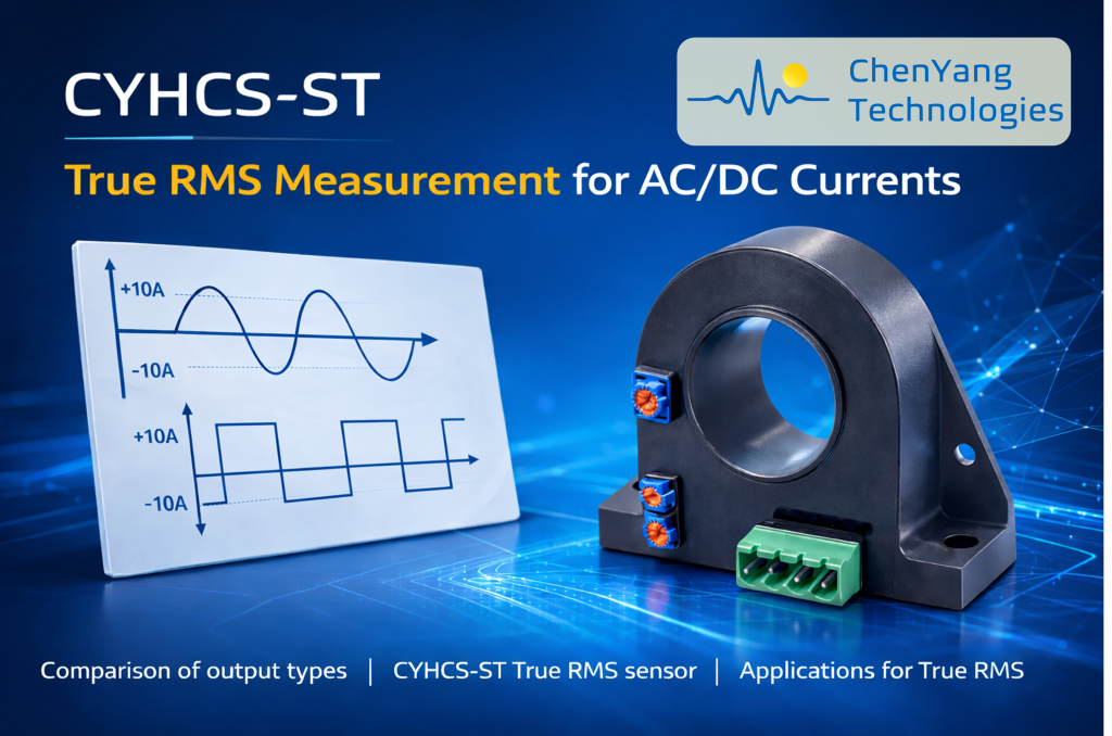
CYHCS-ST – True RMS Measurement for AC/DC Currents
Shuang Qiu Comments 0 Comment
When selecting a current sensor, engineers typically focus on specifications such as:
- Measuring range
- Accuracy
- Galvanic isolation
- Bandwidth
These parameters are undoubtedly important. However, one critical question is often overlooked:
👉 What exactly does the output signal represent?
Not all current sensors deliver the same type of output signal. Even when two sensors measure the same current range with similar accuracy, the physical meaning of their outputs can be fundamentally different.
Depending on the internal measurement principle and signal processing method, the output may represent different electrical quantities. The most common output signal types include:
- Real-time waveform output
- Rectified average value output
- RMS output (often average-based RMS)
- True RMS (TRMS) output
While these terms are sometimes used interchangeably in marketing materials, they do not describe the same measurement result. The distinction becomes especially important when dealing with distorted, pulsed, or inverter-driven currents.
Understanding what the output signal truly represents is essential for accurate system design, reliable protection, and correct power evaluation.
In this article, we will explore:
Chapter 1. Understanding Output Signal Types
Throughout this chapter, we will use two representative examples — a sine wave with a peak value of 10 A and a square wave with a peak value of 10 A — to clearly illustrate how different output signal types respond to identical peak currents.
1.1 Real-Time Waveform Output
A real-time waveform output reflects the instantaneous value of the current. The sensor reproduces the time-dependent signal exactly as it appears at the input. If the input is a sinusoidal waveform, the output is sinusoidal. If the input is a square wave, the output follows the square shape correspondingly. No mathematical interpretation is performed; the signal is simply mirrored in real time.

This type of output is particularly valuable when the shape of the waveform itself carries essential information. Engineers working with oscilloscopes, phase detection, or power factor analysis rely on access to the complete waveform rather than a derived scalar value. In laboratory environments or during power quality investigations, the ability to observe distortion, switching edges, or harmonic content directly is often indispensable. Several Hall effect current sensors from Chen Yang Technologies follow this principle. For example, sensors from the CYHCS-C3S, CYHCS-RC1S, CYHCT-C1TV, and CYHCT-EKCV, CYHCS-D6 series provide outputs that directly reproduce the instantaneous current waveform, as described in their datasheets: “The output of the transducer reflects the real wave of the current carrying conductor.”
However, a real-time waveform output does not directly provide the RMS value of the current. Any control system, PLC, or monitoring unit must perform the RMS calculation independently. This increases computational demand and may add complexity to the overall system design. Therefore, while real-time waveform outputs offer maximum information transparency, they shift the burden of signal interpretation to downstream electronics.
1.2 Rectified Average Value Output
A rectified average value output represents the average of the absolute value of the waveform over one period. Internally, the signal is first rectified so that negative portions become positive, and then the mean value is calculated.
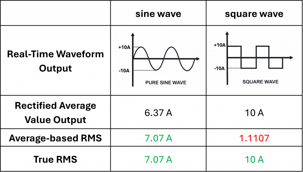
For a sine wave with a peak value of 10 A, the rectified average equals 0.637 times the peak value. This results in an average value of 6.37 A. In contrast, for a square wave with a peak amplitude of ±10 A, the rectified average equals the peak itself, yielding 10 A.
Although both waveforms share the same peak value, their average values differ significantly depending on their shape.
Rectified average outputs are widely used in industrial current sensors because they allow relatively simple and robust signal processing. In many conventional electrical systems—especially those operating with standard 50/60 Hz sinusoidal currents and predominantly linear loads—the relationship between average value and effective value remains predictable. In such environments, rectified average measurements provide reliable and practical information for monitoring current levels. Typical applications where rectified average outputs are commonly used include conventional power supplies, transformer-based systems, industrial power monitoring, and many standard AC measurement tasks.
For this reason, a large number of current sensors from Chen Yang Technologies are based on this output principle, including models such as CYHCS-C1TV, CYHCS-D6C, CYHCS-FAV, CYHCS-KF2V, CYHCS-BTV, and CYHCS-HBC. These sensors provide reliable current monitoring for many conventional industrial applications.
1.3 RMS vs. True RMS
The most critical distinction in current measurement lies in understanding RMS and True RMS.
From a physical perspective, the RMS value is defined as:

This definition highlights an essential concept: the RMS value represents the equivalent DC current that would produce the same heating effect in a resistive load. This is important because many practical electrical effects — such as conductor heating, power dissipation, and the loading of electrical equipment — depend on the electrical power . Since the heating effect is proportional to the square of the current, the RMS value provides a direct measure of the real electrical stress in the system. Therefore, a current sensor intended for power monitoring should ideally provide the correct RMS value.
When we apply the RMS definition to a sine wave with a peak value of 10 A, the effective value is obtained directly from the analytical relationship between peak and RMS:

However, many low-cost instruments labeled as “RMS” do not actually calculate the RMS according to the mathematical definition. Instead, they follow a simplified three-step process:
- Rectify the waveform
- Calculate the average value
- Multiply by a fixed correction factor
For a sine wave, the rectified average value is:

The instrument then multiplies this value by a constant factor:

The factor 1.1107 is not arbitrary. It equals:

Thus, for a pure sine wave:

which reproduces the true RMS value exactly.
This explains why average-based “RMS” meters appear correct under sinusoidal conditions. The proportional relationship between average and RMS is constant for sine waves. The instrument does not truly compute RMS; it merely applies a fixed scaling factor that happens to work for one specific waveform shape.
The situation changes dramatically when the waveform is no longer sinusoidal. Consider a square wave with a peak value of ±10 A. According to the formal definition, the RMS value equals 10 A. The rectified average also equals 10 A. However, an average-based “RMS” instrument multiplies this value by 1.1107 and displays 11.11 A, introducing an error of approximately 11%. The peak value has not changed, yet the indicated effective current becomes incorrect.
This explains why many low-cost RMS instruments can produce misleading results. They rely on a fixed proportional relationship that is valid only for sine waves. Since the ratio between average and RMS for a sine wave is constant, the shortcut works under ideal grid conditions. Once harmonics or waveform distortion appear, the proportional assumption collapses.
Average-based RMS measurement may still be acceptable in purely sinusoidal 50/60 Hz systems with linear loads and minimal harmonic content. In these cases, the waveform closely matches the mathematical assumptions behind the scaling factor.
True RMS measurement becomes essential whenever waveform distortion is present. This includes PWM motor drives, inverter systems, renewable energy installations, variable frequency drives, and advanced power quality analysis. In such systems, the current waveform often contains sharp edges, high harmonic content, and complex switching patterns. The heating effect can no longer be inferred from a simple proportional relationship with the peak value. Using an average-based approximation in these environments may lead to underestimation or overestimation of thermal stress, incorrect protection design, or inaccurate power calculations.
👉 Key Takeaways
Although different sensor outputs may appear similar on a datasheet, they represent fundamentally different physical quantities. Real-time waveform outputs reveal instantaneous behavior. Rectified average outputs provide a mathematical mean of absolute current. RMS represents thermal equivalence. True RMS ensures mathematically correct effective values under all waveform conditions.
Understanding these distinctions is the foundation for selecting the appropriate current sensor for a given application.
Chapter 2. True RMS Current Sensor CYHCS-ST
After understanding why waveform shape fundamentally affects RMS calculation, the next question becomes practical:
How can true RMS measurement be obtained directly from the sensor — without additional computation in the PLC or control system?
The CYHCS-ST is an open-loop Hall effect current sensor specifically designed to deliver a direct True RMS output. It measures AC, DC, pulsed, and irregular waveform currents and converts them into proportional voltage or current signals that already represent the real effective value. The output therefore reflects the actual thermal equivalent current, independent of waveform shape.

Unlike average-based RMS solutions, no waveform-dependent scaling assumption is required. The RMS calculation is internally implemented, allowing the system designer to receive a ready-to-use effective value signal.
Technical Specifications Overview
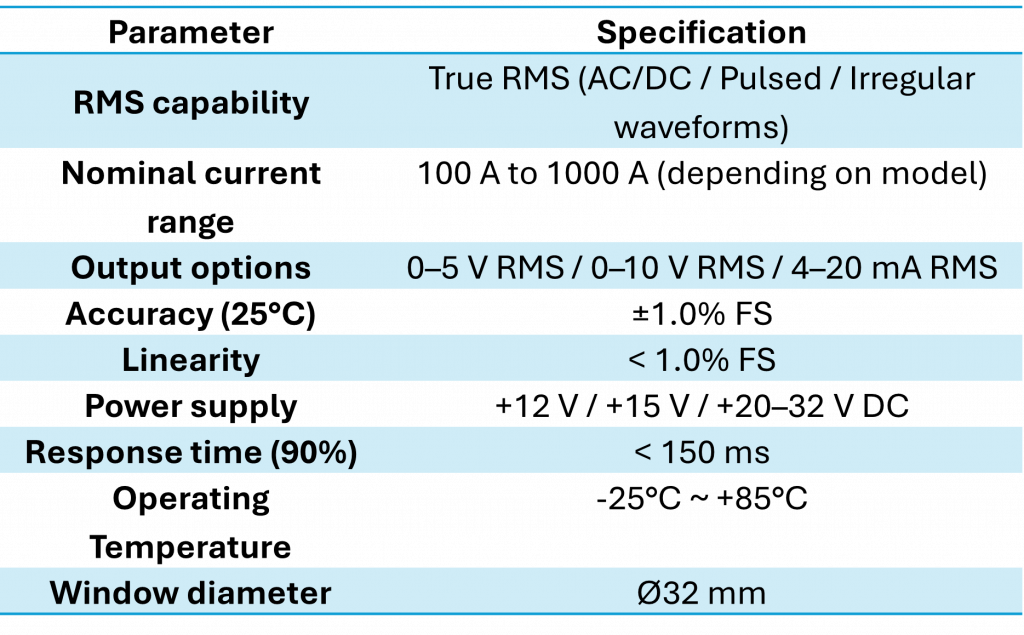
This specification profile positions the CYHCS-ST as a robust industrial sensor suitable for both conventional power systems and applications involving waveform distortion.

Practical Significance
The defining feature of the CYHCS-ST is not merely that it measures current, but that its output directly represents the true effective value. This eliminates the need for external RMS computation and avoids errors introduced by average-based scaling in distorted systems.
In applications such as inverter systems, PWM motor drives, UPS systems, welding equipment, and modern power monitoring environments, waveform distortion is common. A sensor that internally performs true RMS calculation simplifies system design and increases reliability.
By combining galvanic isolation, open-loop Hall architecture, and direct RMS output in a single device, the CYHCS-ST bridges the gap between theoretical RMS accuracy and practical industrial implementation.
Chapter 3. Comparing Output Signal Types
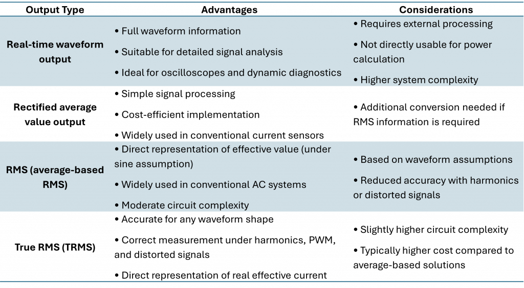
Each output signal type serves different technical purposes. Selecting the right one depends on waveform characteristics and system requirements.
Choosing the Right Output Type
There is no universally “best” output signal type — only the one that matches your application.- For waveform diagnostics → Real-time waveform output
- For simple sinusoidal systems → Rectified average or average-based RMS
- For modern power electronics, inverters, or non-linear loads → True RMS
Chapter 4. True RMS Current Sensor Applications
In many modern electrical systems, current waveforms are no longer sinusoidal.
Switching devices, power electronics, and non-linear loads generate complex waveforms that cannot be evaluated correctly using average-based RMS methods.
In the following applications, True RMS measurement is not optional — it is essential.
4.1 Motor Drives & PWM Systems
Modern motor drives are typically controlled using Pulse Width Modulation (PWM). Although PWM allows efficient and precise control of motor speed and torque, it also generates highly distorted current waveforms characterized by fast switching edges and significant harmonic content. Even when the motor appears to operate smoothly, the underlying current waveform deviates strongly from a pure sine wave.
The thermal behavior of a motor depends on the actual effective current flowing through its windings. If the measurement system relies on average-based RMS methods that assume sinusoidal conditions, the effective current may be underestimated. This can lead to incorrect protection thresholds, insufficient thermal monitoring, and ultimately reduced system reliability.
True RMS measurement evaluates the real effective value of the distorted PWM current, ensuring that thermal load and protection logic are based on physical reality rather than waveform assumptions. This is particularly important in electric vehicles, industrial automation systems, and HVAC motor control applications, where efficiency and long-term reliability are critical.

4.2 Renewable Energy & Inverters
Renewable energy systems such as photovoltaic installations and battery energy storage systems depend heavily on inverter technology. These systems continuously convert between DC and AC while operating under dynamic load conditions. As a result, the current waveforms often contain strong harmonic components, non-sinusoidal shapes, and rapidly changing characteristics. In many cases, the current flow is also bidirectional.
In such environments, waveform assumptions break down entirely. Average-based RMS methods cannot reliably represent the effective current because the signal shape varies continuously. Measurement errors directly influence power calculations, efficiency evaluations, and system monitoring accuracy.
True RMS measurement captures the real effective current independent of waveform shape, harmonic content, or switching behavior. This accuracy is essential for precise energy management, reliable system protection, and optimized economic performance in renewable energy applications.
4.3 Power Monitoring & Protection Systems
In industrial installations and critical infrastructure, current measurement plays a central role in overload protection, short-circuit detection, and power quality analysis. However, modern industrial loads — especially those using switching power supplies or variable frequency drives — often generate highly distorted current waveforms.
Protection systems rely on accurate current thresholds to function correctly. If RMS values are underestimated, overload conditions may not be detected in time, increasing the risk of overheating and equipment damage. Conversely, if the RMS value is overestimated, unnecessary protection trips can occur, leading to costly downtime.
True RMS measurement ensures that protection decisions are based on the actual effective current rather than simplified waveform assumptions. In safety-relevant environments, this distinction is not merely technical — it directly affects operational stability and system safety.
As electrical systems continue to evolve toward power-electronic architectures, the proportion of non-sinusoidal currents increases steadily. In many modern applications, True RMS measurement is no longer an optional refinement but a fundamental requirement for accurate and reliable current evaluation.
Conclusion
Selecting a current sensor is not only about measuring range, accuracy, isolation, or bandwidth.
It is fundamentally about understanding what the output signal actually represents.
In this article, we compared four common output types. There is no universally “best” output type — only the most appropriate solution for a specific application.
However, in today’s power electronics environment — characterized by inverters, PWM control, pulsed loads, switching power supplies, EV chargers, and renewable energy systems — current waveforms are rarely ideal sine waves. Under these conditions:
👉 True RMS significantly simplifies system design, reduces calculation effort, and improves operational safety.
If your application involves distorted, pulsed, or inverter-driven currents, a True RMS output sensor such as the CYHCS-ST is the reliable choice.
You can learn more here:
Integrating the right output signal from the beginning ensures not only accurate measurement — but also a more robust and future-proof system design.
Learn more about Hall effect current sensors in our previous article.