Hall-Effect Vane Sensors: Principle & Applications
- What a Hall-effect vane sensor is
- How does it work
- Its functions and applications
- Its strengths and limitations
- How it compares to other technologies
- Typical application scenarios
What is a Hall-Effect Vane Sensor?
A Vane Sensor is a Hall-based magnetic sensing solution that detects physical states (such as presence, position, or rotational movement ) by mechanically modulating the magnetic flux between a magnet and a Hall sensor using a moving soft magnetic metal vane. When the vane moves in or leaves out the magnetic field region, it interrupts or alters the magnetic flux density that reaches the Hall element. Such a change in flux generates a clear and measurable electrical output. Unlike schemes that sense a moving magnet (e.g., ring-magnet speed sensors), a vane sensor keeps the magnet and Hall element fixed and uses a moving steel vane to modulate the magnetic flux, which the Hall IC converts into an electrical signal.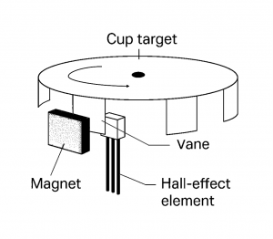
Theoretical Principles
The vane sensor relies on the Hall effect, where the Hall element converts the local magnetic flux into an electrical signal. Building on this principle, a soft-magnetic vane is introduced to mechanically modulate the flux in the gap between the magnet and the Hall IC, enabling both position and speed sensing. For this reason, we begin with the Hall effect as the foundation of the vane sensor’s operation.Hall Effect — the sensing core
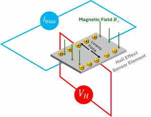
When a current 𝐼 flows through a thin conductor or semiconductor and a magnetic field B is applied perpendicular to the current, charge carriers experience the Lorentz force which pushes them sideways. For more on the Lorentz force (including the right-hand rule for determining the direction), see Hall Effect Current Sensors: An Introduction on our blog. Charges accumulate on one edge, creating a transverse electric field that opposes further deflection. At equilibrium, this field produces a measurable Hall voltage VH across the element. For a rectangular Hall plate of thickness d carrying current I in a uniform field B⟂ (the component normal to the plate), VH is given by the following equation.
 Here, RH is the Hall coefficient (set by material and carrier density). In integrated Hall ICs this is commonly written in application form as
 with kH absorbing geometry and amplification factors, and Ibias is the bias current provided to the Hall element. The schematic below visualizes this relation: a bias current Ibias through the Hall element, a perpendicular magnetic field B⟂ , the resulting Lorentz force, and the transverse Hall voltage VH.
Two immediate design takeaways:
- Only B⟂ matters. The sensor responds to the normal component of the magnetic flux density (units: tesla). Mechanical layout should ensure the vane’s motion causes a clear change in B⟂ at the Hall element.
- Analog vs. switch behavior. A linear Hall output is approximately proportional to B⟂ , a Hall switch adds thresholds (hysteresis) to deliver clean HIGH/LOW edges when B⟂ crosses set points.
Mechanical Vane — mechanically modulating the magnetic field
A mechanical vane is a thin, soft-magnetic insert (typically a steel stamping) that moves through the gap between the magnet and Hall IC (shortly magnet-Hall gap) and changes the magnetic circuit. By modulating the magnetic flux, the vane produces a significant change in the field component at the Hall element, which the IC converts into voltage or digital edges.How does it work?
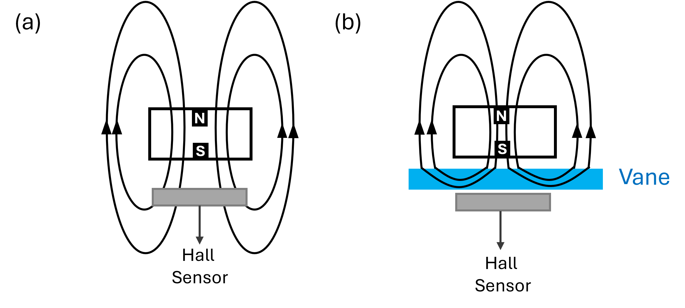
- Flux shaper. The vane’s high permeability (μr ≫ 1) lowers reluctance where it sits, pulling and redirecting flux lines. When the vane enters the gap, it offers a lower reluctance return path and redirects flux away from the Hall element, so the sensedB⟂ drops quickly; when it leaves, the magnetic circuit restores and B⟂ returns to its prior level. Note that the vane does not “block” the magnetic field but just shortens the return path to the magnet’s far pole, thereby shielding the Hall element from the magnet’s field. The schematic below shows how a steel vane redirects the flux, reducing the sensed B⟂ at the Hall element.
- No magnetic target is needed. The object under test (lever, flap, linkage) only drives the vane; it does not need to be magnetic. The vane itself is the soft-magnetic modulator.
- Static position. Vane presence/absence produces two stable field levels for ON/OFF detection or small analog displacement.
- Periodic motion. Repeated interruptions create a clean frequency for speed.
Typical vane materials
- Preferred:
- pure iron (Armco iron)
- low-carbon steel (e.g., DC01, AISI 1008/1010)
- Ferritic stainless steels (e.g., AISI 430)
- Soft-magnetic alloys (e.g., Permalloy, Mu-metal)
- Avoid:
- paper, plastics, aluminum, copper (they do not modulate magnetic flux)
- permanent-magnet grades, materials with high remanence (they introduce instability)
Geometry & placement (what actually matters)
- Gap coverage: the vane must effectively span the useful flux region between magnet and Hall element.
- Vane Thickness: thin enough for low inertia and easy actuation, thick enough to avoid saturation.
- Alignment: keep vane motion orthogonal to the dominant flux path so that insertion causes a monotonic B⟂ change.
Measuring Signal Model & Output Interpretation
The operation of a vane-modulated Hall sensor can be understood by examining:- how the sensed magnetic field evolves as the vane intrudes into and withdraws from the magnetic gap,
- how the Hall threshold mechanism interprets the field, and
- how the resulting switching transitions are translated into a clean, digital output signal.
Field Behavior During Vane Insertion
The figure below shows the sensed magnetic field B at the Hall element as a function of vane position during the insertion of the vane into the flux gap. As the vane begins to enter the sensing gap, its shunting effect on the magnetic flux is initially small, and the Hall element senses a relatively high magnetic field. Once the vane penetrates sufficiently, the field reaches the on-state field region, where it remains approximately constant. As insertion continues, the vane approaches the start-of-rolloff point, after which the sensed field begins to drop rapidly through a sharp transition zone characterized by a steep slope dB/dX. Once the vane is fully inserted, it strongly diverts the flux away from the Hall element, causing the sensed field to settle into a low, nearly constant leakage-field (Off-state) level.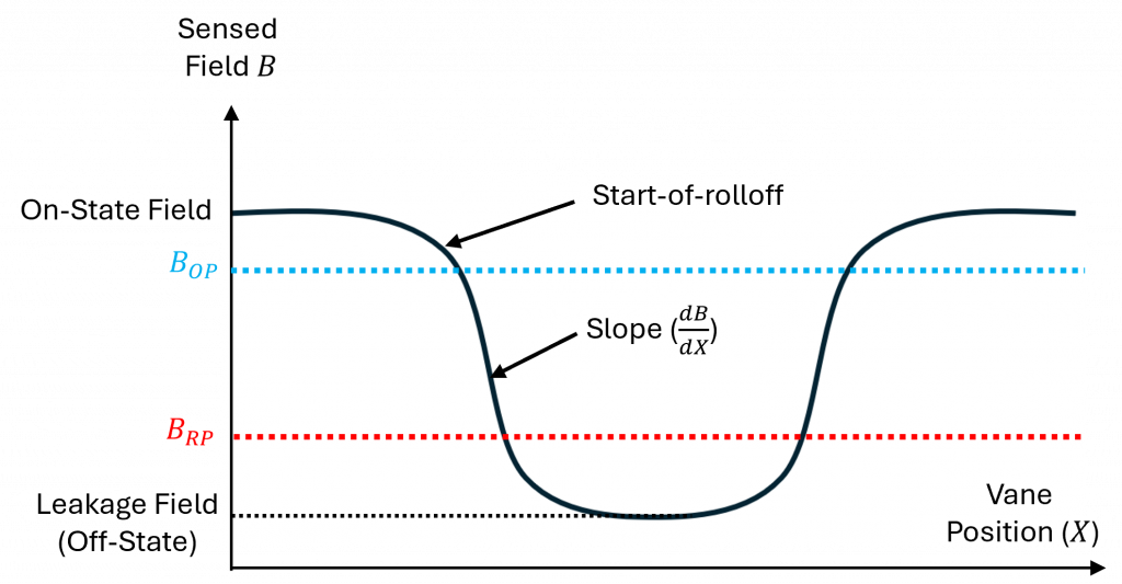
Hall switches interpret this varying field using two magnetic thresholds:
- Operate point BOP : when rises above this level, output goes HIGH.
- Release point BRP : when falls below this lower level, output goes LOW.
On-state field (minimum over all conditions) ≥ BOP,max
Leakage (Off-state) field (maximum over all conditions) ≤ BRP,min
This means, the magnetic design must ensure that the minimum achievable on-state field still exceeds BOP,max , and that the maximum off-state (leakage) field remains below BRP,min.Rolloff Behavior and Output Characteristics
The sharpness and placement of the rolloff region—where the sensed field transitions between the two stable plateaus—are determined by- the magnet strength and size,
- air-gap geometry,
- sensor placement, and
- the vane’s material, width, and thickness.

However, when the magnetic field becomes very weak or very strong, the Hall IC’s output begins to deviate from its ideal linear region and enters a rolloff zone where the voltage response curves rather than remaining perfectly proportional. Even in this non-ideal region, the output still changes monotonically with field strength—and therefore with vane displacement—so it can still provide useful, though coarse, position feedback. Thus, the vane’s modulation of the magnetic flux is expressed at the output as either clean digital transitions or a coarse analog signature, each representing the mechanism’s state and motion.
However, when the magnetic field becomes very weak or very strong, the Hall IC’s output begins to deviate from its ideal linear region and enters a rolloff zone where the voltage response curves rather than remaining perfectly proportional. Even in this non-ideal region, the output still changes monotonically with field strength—and therefore with vane displacement—so it can still provide useful, though coarse, position feedback. Thus, the vane’s modulation of the magnetic flux is expressed at the output as either clean digital transitions or a coarse analog signature, each representing the mechanism’s state and motion.
Function & Application
What can a vane sensor do in real applications? A Vane Sensor enables two core sensing functions, almost all real-world use cases fall naturally into one of these two categories:- Position Sensing
- Speed Sensing
Position Sensing with Hall-Effect Vane Sensors
In position sensing, the vane acts as a mechanical presence/absence element. As the vane enters the magnetic gap, it redirects the magnetic flux and produces a clear transition in the Hall output. This allows the system to detect whether a mechanism has reached a defined position or state.Example: Lid Open–Close Detection
One representative example is safety-cover or lid open–close detection. In this application, a thin steel vane is mounted on the moving cover or lid, while the magnet–Hall assembly is fixed on the stationary housing. When the lid closes, the vane enters the magnetic gap and shunts the flux, switching the Hall output to the “closed” state. Once the lid is opened, the vane leaves the gap, restoring the field and returning the output to “open.” This provides a clean, non-contact, wear-free method to monitor machine-cover status—widely used in appliances, laboratory instruments, and industrial safety interlocks. The figure below illustrates a simplified model of such a setup.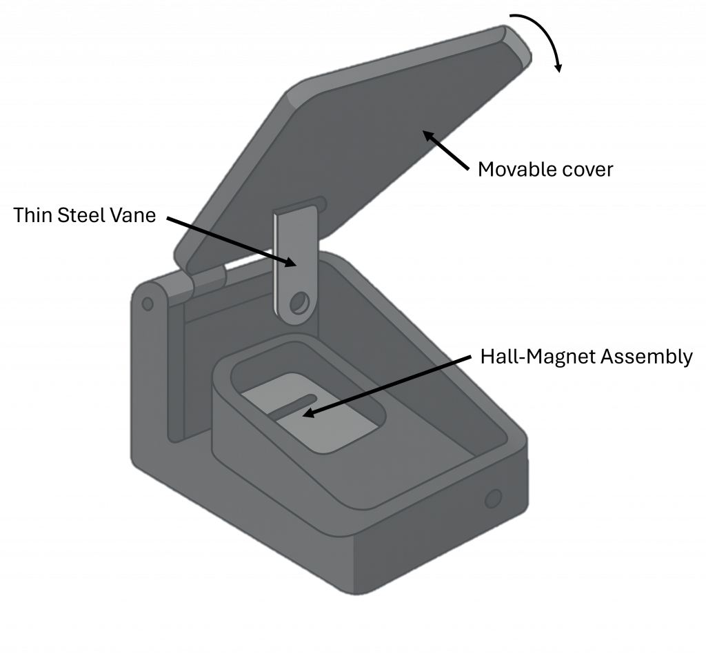
Additionally, other typical position-sensing use cases include:
- HVAC flap position — vane attached to the airflow flap provides end-stop or intermediate-position detection.
- Mechanical linkage / lever end-stop — vane marks the limit position of a mechanical arm or linkage.
- Throttle or intake mechanisms — vane indicates the open/closed state of small air-control elements in compact systems.
- Valve assemblies — vane allows detection of open/closed states in pneumatic or small fluid valves etc.
Speed Sensing with Hall-Effect Vane Sensors
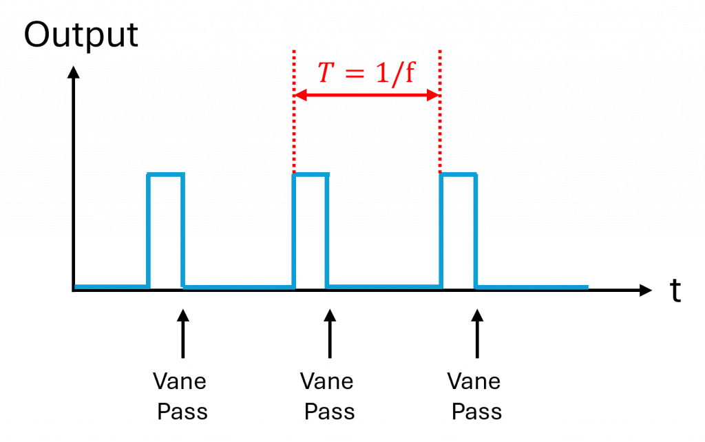
In speed sensing, the vane periodically modulates the magnetic flux as it moves past the magnet–Hall gap. Each time the vane enters the gap, it redirects the field and produces a clean transition in the Hall output. The frequency of these transitions is proportional to the rotational or linear speed of the mechanism, allowing accurate rpm or motion tracking.Example: Ignition System Speed Feedback
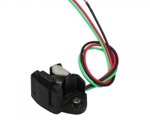
A representative example is the Honeywell 2AV54, widely used for speed feedback in ignition and blower systems. A molded vane wheel rotates with the mechanism in this design, and each vane passes through the magnet–Hall gap to generate a pulse. The resulting pulse train provides precise timing and speed information for ignition control and airflow monitoring. The picture below illustrates such an implementation: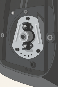
Additionally, other typical speed-sensing use cases include:
- Fan/blower RPM feedback — rotor-mounted vane produces pulses per revolution; pulse frequency gives speed and remains stable in dusty airflow.
- Small DC motor rotation — vane attached to the rotor hub generates pulses for speed regulation.
- Gear or rotor speed in compact mechanisms — vane or tooth-like tabs modulate flux for rpm monitoring in small geartrains.
- Linear motion with repeating mechanical features — notched sliders or shuttles create periodic flux interruptions for linear speed estimation etc.
Strengths, Limitations, and Suitable Use Case
Vane sensors offer a compelling balance of simplicity, robustness, and signal clarity. These characteristics make them well suited for many position- and speed-sensing tasks—especially in environments where dust, oil, vibration, or loose mechanical tolerances challenge optical or contact-based solutions. By mechanically modulating the magnetic flux between a fixed magnet and a Hall element, they generate clean switching edges or stable analog transitions without requiring the target object to be magnetic. Moreover, their integrated magnet–Hall–mechanical package keeps the component and assembly cost low, making vane sensors a cost-effective alternative to optical encoders or more complex magnetic sensing systems.
However, vane sensors are not universally optimal. Applications requiring high-accuracy continuous angle measurements typically rely on linear or multi-axis Hall angle sensors or magnetic encoder solutions. In addition, if the vane cannot reliably enter and exit the magnetic gap under real operating conditions, the feasibility of a vane-based design becomes inherently limited.
In practice, vane sensors work best when the mechanism naturally includes a small moving tab, flap, or tooth that can traverse a compact sensing gap. They provide robust state information, dependable speed feedback during startup, and long-term stability in contaminated environments. On the other hand, designs with large mechanical tolerances, restricted gaps, or requirements for fine angular resolution may be better served by other sensing technologies such as magnetic angle sensors, optical encoders, or variable-reluctance systems.
Competitive Technologies
Different sensing tasks—position detection and speed measurement—are traditionally solved using several well-established technologies. Each operates on a different physical principle and comes with its own strengths and limitations depending on environment, mechanical design, and system targets. The following sections summarize the major competing approaches and how they fundamentally differ from vane-based magnetic flux modulation.Position Sensing Technologies
-
Optical interrupters / optical switches
-
Inductive proximity sensors
-
Reed switches
-
Comparison
| Technology | Principle | Advantages | Limitations |
|---|---|---|---|
| Hall vane sensor | Magnetic flux modulation by vane | Robust, long lifetime, fast response | Requires a magnet and precise vane–gap geometry |
| Optical Interrupter / Optical Switch | Detects beam interruption using light | High resolution, no magnet needed | Sensitive to dust, oil, grease, smoke, alignment |
| Inductive Proximity Sensor | Detects eddy current change from metal target | Non-contact, robust for industrial metal targets | Requires conductive metal target |
| Reed Switch | Magnetically actuated contact closure | No power needed, good for simple on/off detection | Slow response, mechanical wear, bounce noise |
Speed Sensing Technologies
-
Optical encoders
-
Variable-reluctance (VR) sensors
-
Ring-magnet Hall speed sensors
-
Comparison
| Technology | Principle | Advantages | Limitations |
|---|---|---|---|
| Hall vane Sensor | Magnetic flux modulation | Robust, simple stamped-vane target; stable at very low speed and startup | Requires magnet and defined vane gap geometry |
| Optical Encoder | Optical pattern recognition | High resolution, accurate speed feedback | Fragile, alignment-sensitive, cost |
| Variable Reluctance (VR) Sensor | Detects changing reluctance from ferromagnetic teeth | Simple and rugged, no magnet required | Weak signal at low rpm or startup condition |
| Ring Magnet Speed Sensor | Uses rotating multi-pole magnet | High signal amplitude, good for precise speed detection | Brittle sintered materials, limited temp. range |
Typical Application Scenarios of Hall-Effect Vane Sensors
Vane Sensors can be integrated into a wide range of electromechanical systems, particularly where reliable state or speed information is required in compact, contaminated, or mechanically constrained environments. Their ability to modulate magnetic flux using a simple steel vane enables stable detection without the optical alignment, mechanical wear, or material restrictions seen in competing technologies. Below are representative application domains and how vane-based sensing fits naturally into each of them.-
Automotive
-
Industrial Automation
-
Consumer Appliances
-
Robotics & Mechatronics
-
Small Motor Systems
DC Motor Rotation Sensing
A common implementation is small DC motor rotation sensing. A lightweight stamped vane or slotted disk is mounted directly on the motor shaft. As the shaft turns, each vane edge passes through the magnet–Hall gap and generates one pulse. The controller converts pulse frequency into motor speed and monitors for stall or overload conditions. Because the vane has very low inertia and requires no optical components, it is highly reliable in dusty, oily, or vibration-prone motor housings.Gear or Rotor Speed Monitoring
Gear or rotor speed monitoring in compact mechanisms is another frequent use case. Here, a single tooth, tab, or miniature vane is integrated into the gear or rotor structure. As it rotates past the sensing gap, it produces periodic flux modulation that the Hall IC converts into a pulse train. This method delivers stable speed feedback even in tight spaces where optical encoders cannot fit and where VR sensors can struggle during the initial stages of motion. It also allows designers to instrument only one gear in the train while still achieving accurate system-level rpm or timing feedback. Together, these characteristics make Hall-effect vane sensors particularly suitable for compact pumps, cooling modules, small actuator motors, and other motion-control assemblies where reliable startup detection and clean pulse generation are essential.Application Domains and Why Vane Sensors Fit Well
Across these domains, the vane mechanism provides a simple and robust way to convert physical movement into reliable electronic information — without requiring the target object to be magnetic. The table below summarizes these application categories and the key reasons why vane sensors fit well in each case.| Application Category | Example Use Cases | Why does Vane Sensor Fit Well |
|---|---|---|
| Automotive | • Throttle valve • HVAC flap control • Gear actuator feedback | • Tolerant to temp. variation and contamination. • Compatible with legacy Honeywell/Siemens vane sensor formats |
| Industrial Automation | • Machine covers / safety-interlocks • Pneumatic valve blocks • Mechanical linkage / lever end-stops • Valve assemblies | • Reliable in oil, grease, and dust • Non-contact, vibration-immune switching |
| Consumer Appliances | • Fan / blower RPM feedback • Small motorized subsystem monitoring • End-stop detection for appliance mechanisms | • Stable sensing in dusty / humid airflow • Low part count, easy to integrate |
| Robotics & Mechatronics | • Mini-actuator position detection • Robotic joint homing / linkage feedback • Throttle or intake mechanism state sensing | • Clean edges with hysteresis • Vibration-resistant in small actuators |
| Small Motor Systems | • Small DC motor rotation sensing • Gear / rotor speed sensing in compact mechanisms • Compact pumps and cooling modules | • Works at startup condition • Ideal for closed-loop and stall detection |
Conclusion
In conclusion, vane-based magnetic flux modulation provides a practical, reliable, and cost-efficient sensing approach for detecting mechanical position and speed across automotive actuators, HVAC mechanisms, appliance fans, compact motors, industrial safety interlocks, and other electromechanical systems. Because the target does not need to be magnetic, and because the sensing remains stable under dust, oil, temperature variation, and optical contamination, Vane Sensors offer clear advantages in many real-world environments where optical or contact-based techniques struggle. At ChenYang Technologies, we continuously develop and refine different Hall-effect Vane Sensor configurations to support diverse mechanical structures, speed ranges, and environmental requirements. Many of our vane sensor designs are also compatible with established Honeywell and Siemens vane-type formats, providing practical replacement options for maintaining or upgrading legacy automotive and industrial systems. Based on customer specifications, we offer a broad selection of standard Vane Sensor products to help optimize sensing performance for specific applications. We invite you to explore more practical, innovative, and cost-effective products on the ChenYang website.Referances
- Edward Ramsden, Hall-Effect Sensors: Theory and Application, 2nd Edition, Newnes/Elsevier, 2011.
- Honeywell, “High-Resolution Magnetic Speed Sensors (VRS Series) – Product Datasheet,” available at: https://prod-edam.honeywell.com/…/vrs-magnetic-speed-sensors…
One thought on “Hall-Effect Vane Sensors: Principle & Applications”