Hall Effect Current Sensors: An introduction

In this article, we want to introduce Hall Effect current sensors to you. Current Sensing is an important process for the evaluation, control, and diagnosis of electrical systems. Traditionally, you use current sensing for circuit control and protection. Due to technological progress, people use current sensing in performance optimization and monitoring as well. Thus, you can find Current Sensors in many application fields like:
- Current and voltage control
- Inverter
- Servo motor
- Generators
- Automobile electronics
- Telecommunication
- Battery management systems
- Wind turbines
- photovoltaic-equipment
- etc.
One commonly used method is resistive current sensing using a shunt-resistor. It exploits the voltage drop on the shunt-resistor to calculate the current flowing through the resistor using the formula
![]()
But resistive current sensing has a few disadvantages. First, there is a lack of electrical isolation between the power-handling and measurement circuit. As you measure the voltage drop at the terminals of the resistor, you have to integrate the current-sensing instrument into the circuit being monitored. So, due to safety concerns, you can only use resistive current sensing in the high-voltage application, if you can guarantee the separation between the power-handling circuit and measurement circuit by using additional electronics. Furthermore, the voltage drop on the shunt-resistor leads to energy loss. To minimize the losses, the resistor value should be as low as possible.
Because of these issues, Hall Effect Current Sensors are widely used as well. They are a reliable solution for non-contact current measurements with high accuracy. The galvanic isolation between the sensor and current guarantees a high degree of safety. Furthermore, Hall Effect Current sensors have a simple structure and low energy losses.
Physical Basics
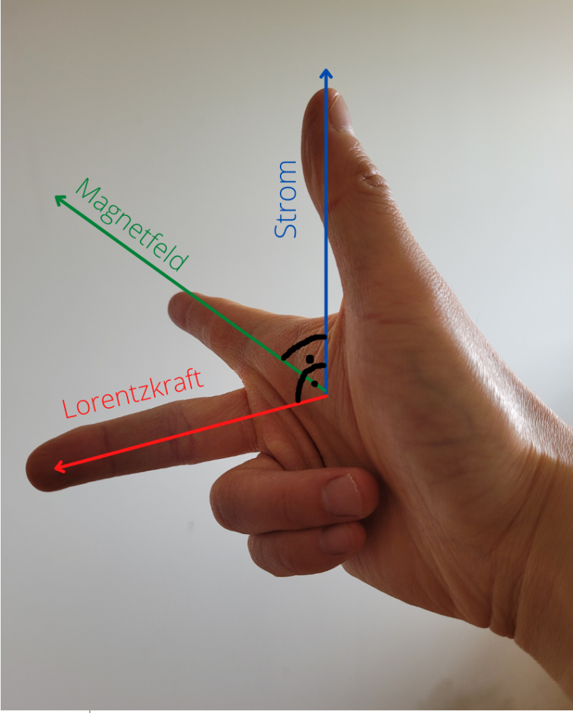
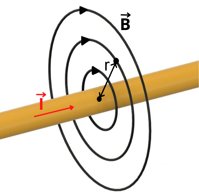
Hall Effect Current Sensors use the Hall Effect to measure the current flowing through a conductor by detecting the strength of the magnetic field, which is generated by the current-carrying conductor. The American physicist Edwin Hall discovered this effect in 1879. When an electric current flows through a semiconductive material, the electrons within move in a natural straight line. However, if the conductor is exposed to a magnetic field, the Lorentz force, which acts according to the right-hand rule (see fig. 1), causes the electron’s movement to change its direction.
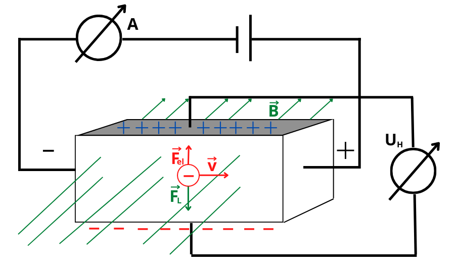
The Lorentz force causes electrons to move to one side of the conductor, resulting in a potential difference in the conductor called the Hall voltage UH.
The following equation describes the Hall Voltage:
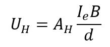
Ie represents the supply current in the Hall element while B stands for the magnetic flux density, d for the thickness of the sample, and AH for the so-called Hall constant.
The Hall voltage UH is directly proportional to the input current Ie and the magnetic field strength B. Hall effect sensors use this fact to measure a wide variety of parameters such as current strength, speed, or position.
Hall Effect Current Sensors
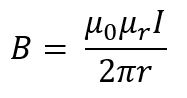
With the following equation, you can calculate the magnetic flux, generated by a current-carrying conductor.
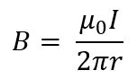
Here, μ0 and r represent the permeability of the air and the radial distance between the observed point and the center of the conductor. It is important to note, that the magnetic field B is directly proportional to the conductor current I.
If you apply an input current to a Hall element and expose the element to a magnetic field, you generate the Hall voltage UH is generated. It can be used to determine the conductor current I.
However, this measurement technique has some issues. First, the generated magnetic field is very weak at small current flows. For example, with a current strength and a radial distance of 20A and 2 cm, a magnetic field of only about 2 gausses is created. Considering that the Earth’s magnetic field is approximately 0.5 Gauss, there is a 25% chance of error. Thus, the measurement method is not suitable for the measurement of small currents, since external environmental influences can significantly falsify the measurement results.
In addition, the method proves to be very sensitive to positioning errors between the conductor and the sensor. So, strict position monitoring of the sensor is required.
The usage of a ferromagnetic core can solve these problems. Inside the core, the magnetic field is amplified by the permeability of the core μr. With the following formula, you can determine the magnetic field in the ferromagnetic core.
By placing a Hall element in the air gap of the toroid, you generate a much larger Hall voltage. Furthermore, the Hall voltage is less dependent on the exact positioning of the current-carrying conductor, since the majority of the magnetic flux basically flows in the toroidal core and only diverges slightly.
Various types of Hall effect sensors for current measurement exist. In general, you can distinguish between “open loop” and “closed loop” sensors. In the following, we discuss these two sensor types in detail.
Open-loop Hall Effect Current Sensors
Figure 5 shows the structure of an open-loop sensor. It consists of the following components:
- a Hall element
- a toroidal (or rectangular) core with high permeability
- Electronics for signal processing
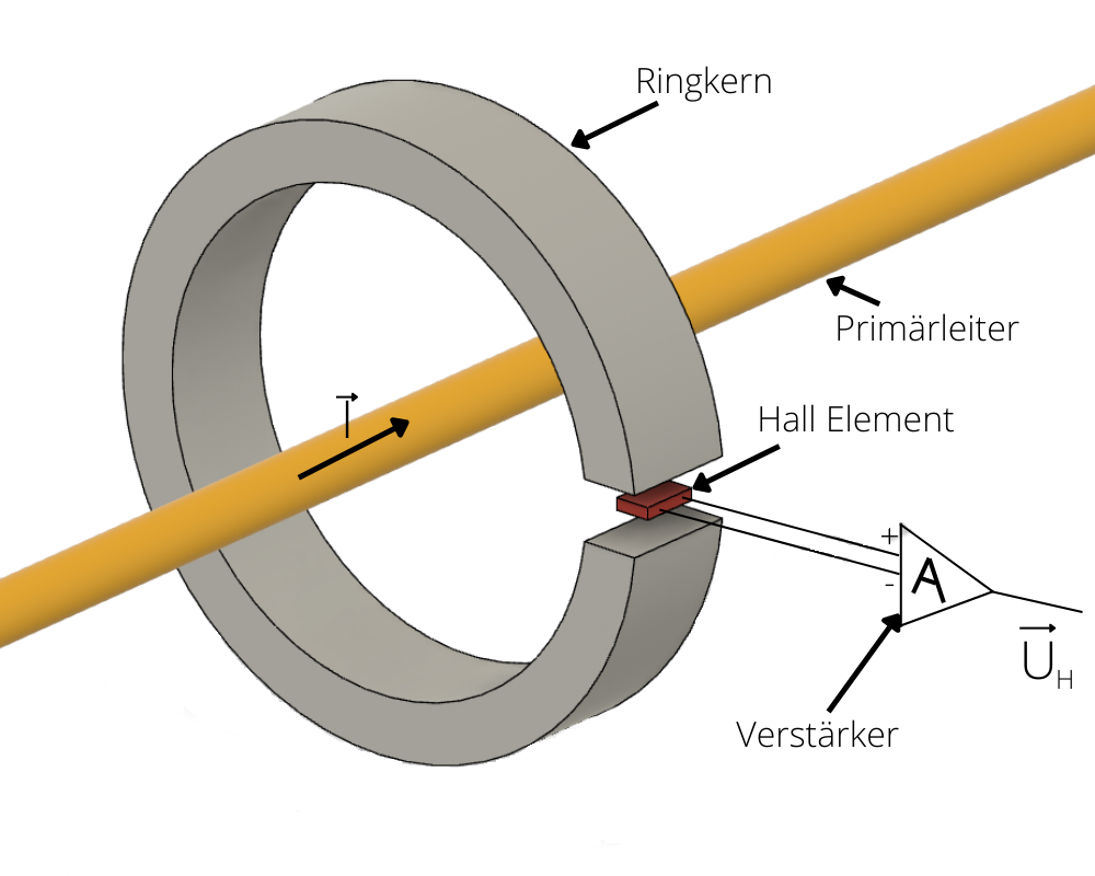
The primary conductor runs through the sensor’s window and generates a magnetic field when current flows. Due to its high permeability μr, the toroidal core significantly amplifies the magnetic field. A Hall element is placed in the air gap of the toroidal core and generates a Hall voltage which is subsequently amplified and processed by a signal processing circuit. The circuit can be very basic and only amplify the signal. Or you can use a complicated compensation circuit that corrects errors in the signal offset or in the Hall effect drift. Often, people use a differential amplifier with high gain, input impedance, and offset correction.
Open-loop sensors offer excellent value for money and are ideal for applications where you have to minimize power consumption, size, and weight. They are lightweight, inexpensive, and do not suffer significant damage from excessive overcurrent. These properties make open-loop sensors extremely popular in application areas such as:
- Battery operated circuits
- Drives with low linearity and accuracy requirements
- The current measurement of fans and pumps
- Welding equipment
- Battery management systems
- Applications with uninterruptible power supplies
However, above a certain magnetic field strength, material saturation occurs, which leads to amplification and linearity errors. Furthermore, open-loop sensors are more susceptible to temperature fluctuations and noise. These limitations limit the accuracy of open-loop sensors and prevent their application in precision measurements.
For high-precision measurements, we recommend using closed-loop sensors.
Closed Loop Hall Effect Current Sensors
Figure 5 shows the structure of a closed-loop sensor. It consists of the following components:
- a Hall element
- a toroidal (or rectangular) core with high permeability
- A coil that is wound around the toroid
- Electronics for signal processing

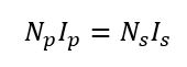
Like many other electronic systems, closed-loop sensors use negative feedback to correct linearity and gain errors. A negative feedback current Is, which drives the coil around the toroidal core, opposes the input current Ip. The coil generates a magnetic field that counteracts the primary conductor’s magnetic field and completely compensates for the magnetic flux in the toroidal core. As a result, there is no material saturation even with high currents in the primary conductor.
The negative feedback current results from the output of the hall element. The Hall voltage UH is converted to the required feedback current by an amplifier and connected to the coil. Using the following equation, you can determine the required feedback current.
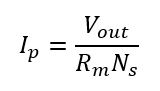
If you require a voltage as the output signal, you connect a resistor Rm between the sensor output and ground. In this case, you derive the primary current from the following formula.
Compared to open-loop sensors, the closed-loop structure results in better accuracy and linearity, as well as improved resistance to noise and temperature drift. This means that you can use closed-loop sensors for precision measurements of high currents as well. Closed-loop sensors are also suitable in extreme environmental conditions such as extreme temperatures or strong electrical noise. Therefore, people use closed-loop sensors in the following areas of application:
- Variable speed drives with high accuracy and linearity requirements
- Servo controls
- Overvoltage protection
- Industrial AC and DC drives
- Robot controls
- Etc.
However, closed-loop sensors require an additional coil and more electronic components. This results in a larger and more expensive sensor with higher power consumption than open-loop sensors. Stability problems can also occur in closed-loop sensors. An unstable system will overreact to an abrupt change in input current. Therefore, you need to properly regulate the system.
Conclusion
Hall current sensing plays an important role in the evaluation, control, and diagnosis of electrical systems, and has proven its advantages over resistive current sensing technology. Thus, Hall Effect current sensors are often utilized in performance optimization and monitoring, for automobile electronics, renewable energy equipment, as well as current and voltage control in many other industrial applications.
ChenYang Technologies offers a wide range of different Hall Effect current sensors for multiple applications. Based on the requirements, ChenYang Technologies provides customers with the best solution for their applications. We offer even custom-made products with special requirements.
4 thoughts on “Hall Effect Current Sensors: An introduction”