Photoelectrical Induction Current Sensors
Introduction to Current Sensing and Measurement
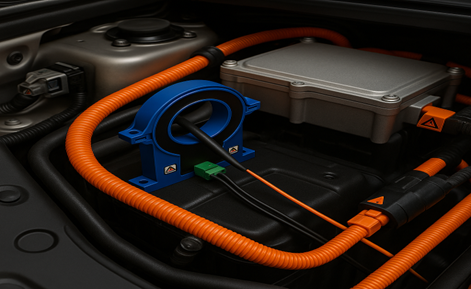
In the world of electrical engineering, current sensors act as the “ammeters” of electric current measurement. They provide critical insights into how electricity flows through a system. As a result, we can monitor performance, prevent overloads, and enable smarter, safer electronics. In this article we will introduce Photoelectrical Induction Current Sensors.
Among the diverse range of current sensors, one cutting-edge technology stands out for its precision and non-invasive approach: Photoelectrical Induction Current Sensors, is a type of non-contact sensor that uses light to measure electric current with high precision and safety. Unlike traditional methods, offering unparalleled safety and accuracy in demanding applications.
What Is Electrical Current?
Electric current is the flow of electric charge through a medium, typically a conductive material such as copper or aluminum. It is driven by a voltage (potential difference) and occurs when free electrons move under the influence of an electric field. Specifically, there are two main types of current:
- Direct Current (DC): Unidirectional or bidirectional flow (e.g., batteries).
- Alternating Current (AC): Periodically reversing flow (e.g., power grids).
Mathematically, current is defined as: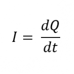
Where:
- 𝐼= electric current (A)
- 𝑄 = electric charge (C)
- 𝑡= time (s)
Current magnitudes range from a few microamperes in electronics to many kiloamperes in industrial systems. Accurate current measurement is critical for safety, performance optimization, and diagnostics.
How Current Sensors Work
A current sensor is an electronic device which measures the flow of electric current in a conductor, converting it into a proportional signal, such as voltage, current, or digital output. It then turns this information into a signal (either analog or digital) that other electronic systems can use. This helps systems monitor how much power is being used, adjust performance in real time, and detect problems before they cause damage.
In particular, they come in two main categories:
1.Contact (Direct) Sensors:
- Use shunt resistors or inline configurations.
- Measure voltage drop (Vdrop) across a known resistance (R) via Ohm’s Law:
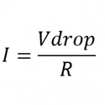
Where:
- I = current under test
- Vdrop = measured voltage
- R = resistance
2.Non-Contact (Indirect) Sensors:
- Utilize electromagnetic or optical principles to measure current externally.
- Preferred in high-voltage, high-frequency, or safety-critical environments.
Photoelectrical Induction Current Sensors offer a non-contact method for current measurement, utilizing optical techniques to achieve electrical isolation and precise detection. While they provide advantages in specific high-voltage or EMI-sensitive environments, they complement other non-contact technologies such as Hall effect sensors, each suited to a particular application requirement.
Photoelectrical Induction Current Sensors
Driven by the need for high precision, electromagnetic interference (EMI) immunity, and electrical isolation, photoelectrical induction sensors have emerged as a great solution. Unlike traditional sensors, these sensors measure current by using light interaction with the electromagnetic fields generated by current flow, eliminating the need for direct electrical contact.
They provide accurate current measurements while maintaining electrical isolation between the measuring system and the conductor. This non-intrusive approach is particularly advantageous in high-voltage applications and environments where traditional contact-based sensors may pose safety risks or be susceptible to electromagnetic noise.
The Working Principle of Photoelectrical Sensors
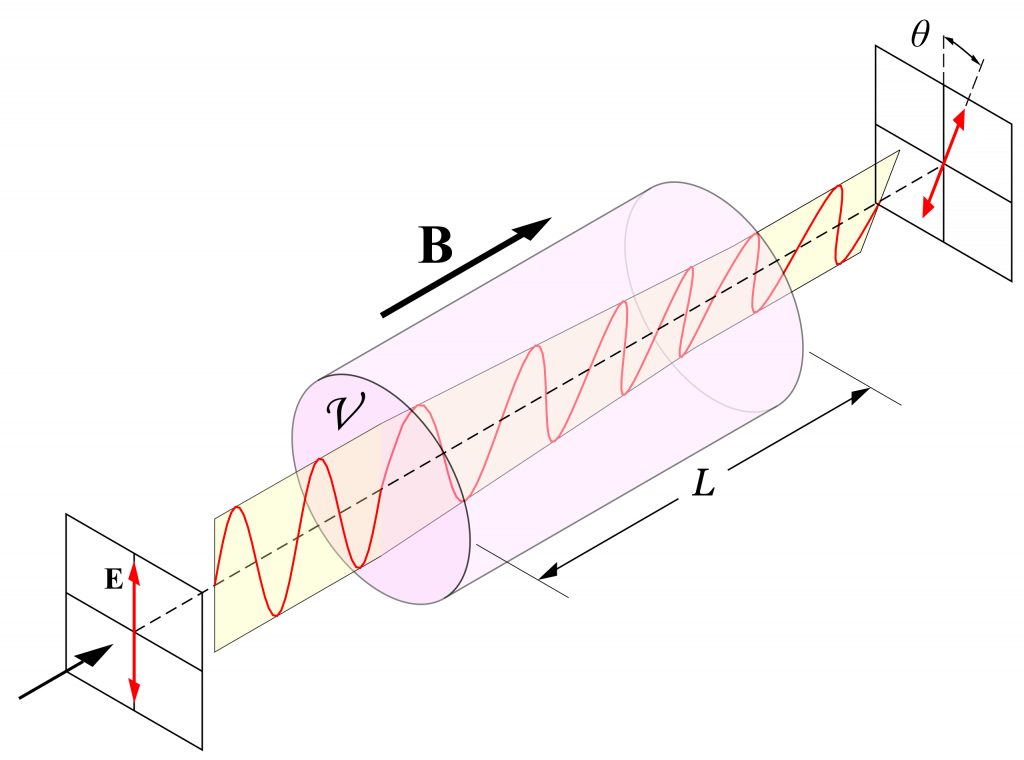
The Faraday Effect:
The movement of electric charge through a conductor, as governed by Ampère’s law, establishes a magnetic field around it. In advanced sensing architectures, this field interacts with a proximate optical component (e.g., fiber or crystal), modifying specific attributes of transmitted light, such as polarization, phase, or intensity, to encode current information into the optical signal.
So, what exactly is an optical signal?
An optical signal is a beam of light, typically infrared or laser, that carries information by modulating its properties. In the context of photoelectrical induction current sensors, this light passes through a transparent or optically active medium, such as a crystal or fiber. As the magnetic field generated by the current interacts with this medium, it alters the light’s intensity, polarization, angle, or phase.

This modulated light is then detected by a photodetector, which converts the changes in the light signal back into an electrical output that is proportional to the measured current. The entire process is non-contact, fast, and electrically isolated from the circuit, making it ideal for high-precision and safety-critical applications.
This phenomenon, specifically the rotation of the light’s polarization under the influence of a magnetic field, is known as the Faraday Effect. The rotation angle (θ) of the polarization is directly proportional to the magnetic field strength (B), the length of the optical path (L), and the material’s Verdet constant (V), as described by the equation: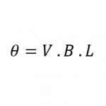
Main Components of a Photoelectrical Induction Current Sensor
Key components include:
- Light Source: A laser diode or LED serves as the light source, emitting a beam directed through an optical path.
- Optical Medium: Material (e.g., Bi₄Ge₃O₁₂ crystal or silica fiber) where light interacts with the magnetic field.
- Photodetector: Converts modulated light (intensity, polarization, or phase changes) into electrical signals.
- Signal Processing Unit: Amplifies, filters, and digitizes signals for analysis.
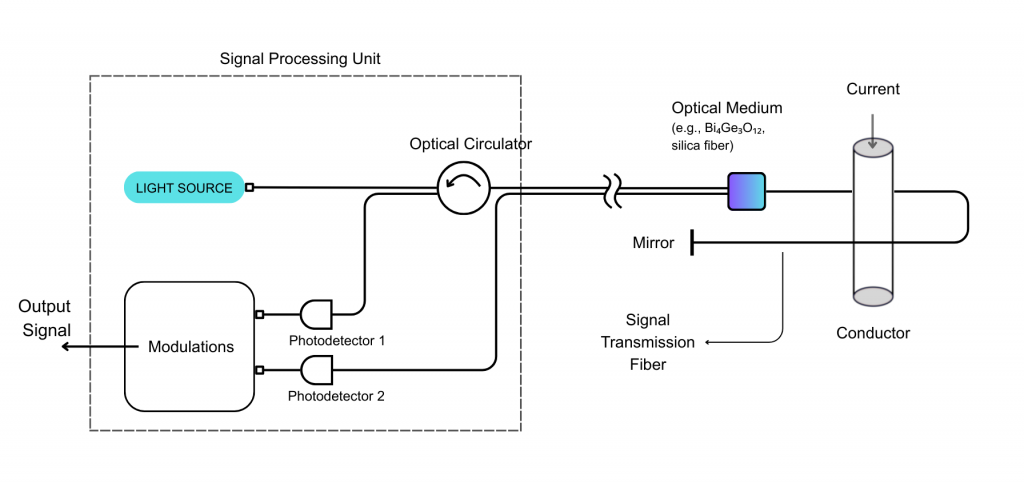
Figure 4 – Components of Photoelectrical Induction Current Sensors
Signal Processing Workflow in Photoelectrical Induction Sensors
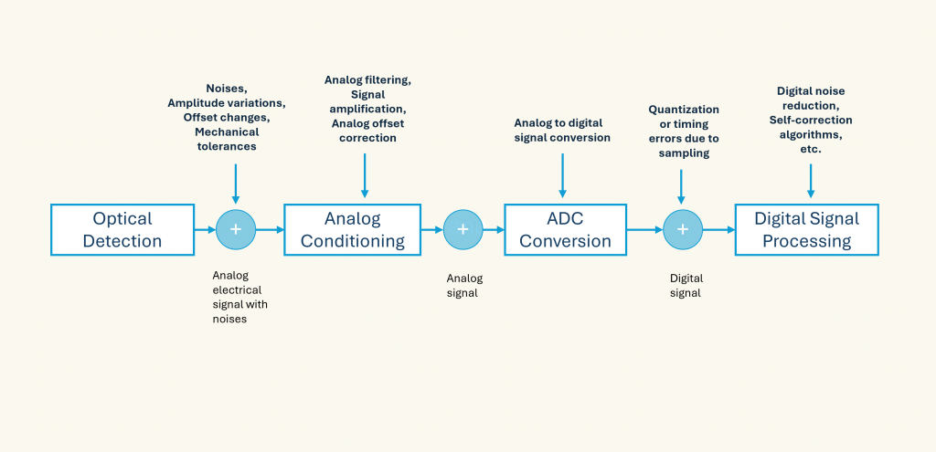
Processing Steps:
The modulated light, affected by the current-induced electromagnetic fields, undergoes several processing steps that will help us get the most accurate results, these steps are:
- Optical Detection: Converts light variations into an analog electrical signal. This signal carries useful data but is also affected by noise, amplitude variations, offset changes, and mechanical tolerances.
- Analog Conditioning: Applies analog filtering, As a result it removes noise, amplifies the signal for clarity, and corrects any offset.
- ADC Conversion: The analog signal is converted into a digital one for processing. Thus, small errors, like quantization or timing inaccuracies, may occur, but these are corrected in the final Digital Signal Processing step.
- Digital Signal Processing: Applies various algorithms to correct signal distortions and enhance data quality such as Digital Noise reduction And Self-Correction.
Advantages of Photoelectrical Induction Current Sensors
Photoelectrical Induction Current Sensors offer several notable advantages that make them highly suitable for various applications. For example, their design ensures electrical isolation, as they measure current without direct contact with the conductor, enhancing safety and minimizing interference.
These sensors exhibit high sensitivity, enabling the detection of minute current changes, which is crucial for precise monitoring.
They also possess a wide bandwidth, allowing accurate measurement of both alternating current (AC) and direct current (DC) across a broad frequency spectrum.
Furthermore, their compactness, often achieved through the use of optical fibers, facilitates flexible and space-efficient installations in diverse environments.
When to Use Photoelectrical Current Sensors
Ideal for:
- High-Voltage Systems: Ideal for applications involving high voltages where safety is paramount.
- EMI-Prone Environments: Suitable for environments with significant electromagnetic interference.
- Accurate AC and DC Measurements are Needed: Capable of precise measurements across a wide frequency range.
- Precision Applications: Medical devices, laboratory equipment.
- Non-Intrusive Requirements: Retrofit installations or sealed systems.
Comparative Overview of Current Sensor Technologies
This table provides a clear comparison of the key performance parameters for each sensor type, aiding in selecting the technology based on application requirements.
| Parameter | Photoelectrical Induction | Magnetic Modulation | Hall Effect |
| Measurement Principle | Faraday Effect (light polarization via magnetic fields). | Detects magnetic permeability changes in current-carrying conductors | Hall voltage from magnetic field |
| Electrical Isolation | Excellent | Good | Good |
| Accuracy | High (<0.2-0.5%) | High (<0.2-1%) | Good (0.5%) |
| Bandwidth | Moderate | Wide | Moderate |
| Response Time | (350ms) | (<15ms-400ms) | Fast (-200ms) |
| Temperature Stability | Moderate | Good | Moderate |
| Cost | High | Medium to High | Low |
| Size | Large to Medium | Medium | Small |
| EMI Immunity | Excellent | Good | Moderate |
| AC/DC Measurement | Both | Primarily AC | Both |
| Typical Applications | High-voltage power systems, renewable energy installations, and environments with strong EMI where high isolation and precision are required. | Industrial automation, motor control systems, and applications requiring high-precision AC current measurements. | Automotive systems, battery management, consumer electronics, and general-purpose current sensing where cost and size are critical factors. |
This comparison highlights the distinct strengths of each current sensing technology. Photoelectrical Induction Sensors provide exceptional electrical isolation and EMI immunity, making them ideal for high-voltage and sensitive environments. Magnetic Modulation Sensors offer high accuracy and wide bandwidth, particularly beneficial for precise AC current measurements in industrial settings. Hall Effect Sensors are notable for their compact size, low power consumption, and high reliability. Their solid-state, contactless design ensures long operational life with minimal maintenance, making them suitable for battery-powered and space-constrained applications such as automotive systems and consumer electronics.
Conclusion
Photoelectrical Induction Current Sensors revolutionize current measurement by combining optical precision with non-contact safety. Their ability to operate in high-voltage, EMI-heavy environments, while delivering unmatched accuracy, makes them a great option in modern electrical systems. As industries increasingly prioritize safety and efficiency, these sensors will play an important role in advancing smart grids, renewable energy, and electrified transportation.
At ChenYang Technologies, we specialize in Photoelectrical Isolation Current Sensors, such as the CYCT01-xnS3, CYCS-xnS0, and CYCS-xnS3, which are engineered for environments that require both precision and electrical isolation. These sensors use optoelectronic components like LEDs and photodetectors, to safely transmit current information across isolated circuits.
Photoelectrical Isolation and Photoelectrical Induction sensors share key similarities: both use light as a medium for signal transmission, provide non-contact current measurement, and deliver high isolation performance. This makes Photoelectrical Isolation Current Sensors a practical and effective alternative, offering many of the same benefits, but with simpler integration and competitive cost-efficiency.
References:
[1] Wikimedia Commons contributors. File:Faraday-effect.svg [Internet]. Wikimedia Commons; 2023 Oct 13, 18:02 UTC [cited 2025 Sep 12]. Available from: https://commons.wikimedia.org/w/index.php?title=File:Faraday-effect.svg&oldid=811570174.
One thought on “Photoelectrical Induction Current Sensors”