Hall Effect Gear Tooth Sensors: an Introduction
Introduction
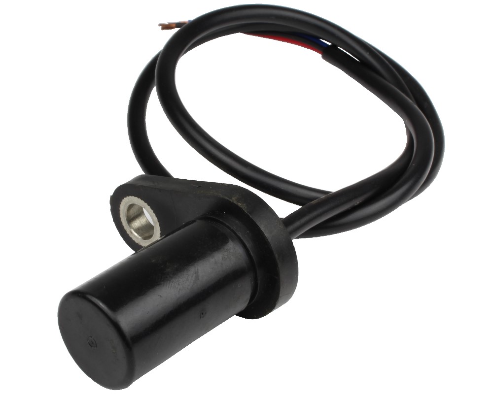
Hall Effect Gear Tooth Sensors are an established and inexpensive technology for the measurement of position and rotational speed. By sensing the magnetic flux variation in the air gap between a magnet and passing ferrous gear teeth, they generate a pulse signal with a frequency proportional to rotational speed. Their quick response time, high operating temperature range as well as their contamination, and EMI immunity have turned Hall Effect Gear Tooth Sensors into popular sensing solutions for many different industries like automation, automotive, and renewable energy.
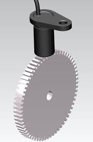
Figure 1: Hall Effect Gear Tooth Sensor
In gearbox wind turbines, gear-tooth design deficiencies and gearbox failures occur at specific bearing locations and later advance into surface wear, bearing debris as well as misalignments of gear teeth. These result in scheduled shutdown time for maintenance work, which is costly and time-consuming. Hall Effect Gear Tooth sensors are utilized to proactively optimize the operation of gearbox wind turbines. They monitor the speed and position of the gears and consequently reduce maintenance work and operation costs.
In this article, we take a closer look at this useful technology.
Structure of Hall Effect Gear Tooth Sensor
A Hall Effect Gear Tooth Sensor consists of a Hall Effect sensor IC, a permanent magnet, and a target gear. The IC is placed on the face of a bias magnet and detects the addendum of the target gear by interpreting the flux variation in the air gap between a magnet and passing ferrous gear teeth. As a gear tooth crosses the magnet surface, the magnetic flux becomes attracted to the lower reluctance path of the ferrous gear. This results in an increase of flux density measured by the Hall element, which is outputted as a pulse signal for further signal processing.
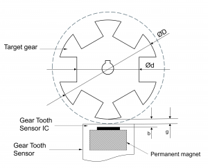
Figure 1: Working Principle of Hall Effect Gear Tooth Sensors
Categories of Gear Tooth Sensors
To create Hall Effect Gear Tooth Sensors, many schemes, that take advantage of the nature of vector flux field, have been developed. But most of them can be categorized into two categories:
- single-point sensors
- differential sensors
They differ in the magnetic field features being measured and how the results are interpreted into a signal. Thus, they have unique characteristics and are used in different applications.
Single-point sensors like the CYGTS101DC from ChenYang Technologies measure the magnitude of a magnetic field and compare the result to a threshold. If the measurement exceeds the threshold, the sensor’s output changes to a target-present state. Below the threshold, the sensor switches to a target-absent state. In many single-point sensors, the thresholds dynamically adapt to the operating conditions. They are considered ac coupled sensors which require the target to move with a minimum speed to work properly.
On the other hand, differential gear-tooth sensors are based on magnetic field detection and thus react to the leading and trailing edges of gear teeth. Leading edges turn the sensor into the target-present state while trailing edges reset the sensor. This makes these sensors useful in applications like automobile ignition systems, where the information when the edge of the target tooth passes by, is of great importance. Furthermore, these sensors often don’t require a minimum speed to detect passing gear teeth. Examples of differential sensors are CYGTS101DC-S, CYGTS104X, and CYGTS104U from ChenYang Technologies.
Benefits of Gear Tooth Sensors
Hall Effect Gear Tooth sensors are compact and inexpensive devices, which can reliably measure rotational speed with high accuracy. With a 25-tooth target, most gear tooth sensors can measure rotational speeds up to 60000 RPM. Furthermore, their high operating temperature range and immunity against contamination and EMI make applications under rough operation conditions possible.
Compared to Vane sensors, Gear Tooth sensors are highly popular because of their easy implementation in machines and devices. Usually, speed sensors are the last part, which developers take into account in machine design. Thus, speed sensing from features that either already exist or are easy to add, such as gears, keyways, holes as well as pinions is highly sought after. That way, high costs for redesign and retooling can be prevented. With Hall Effect Gear Tooth Sensors, finding or making a suitable target becomes an easy task.
Limitations of Gear Tooth Sensors
But there are still some limitations and challenges linked with the application of Hall Effect Gear Tooth Sensors. Firstly, many gear tooth sensors only detect target features as they move past them. They do not have the ability to truly register the presence of a target and thus are not suited for use as proximity detectors.
Furthermore, Hall Effect Gear Tooth Sensors primarily measure displacement and not speed. Speed is measured indirectly by counting the number of fringes in a specific time frame. That causes the problem, that the speed resolution is proportional to the rotational speed. The greater the rotational speed, the better the resolution. This does not pose a problem in the case of high speeds. But for low speeds, this results in bad resolutions, which might not fulfill the requirements of many industrial applications.
To overcome the disadvantages in low-speed ranges, ChenYang Technologies has developed the Hall Effect Gear Tooth Sensor CYGTS102DC. Besides the traditional square wave signal, this sensor additionally outputs a sinusoid one. By measuring the phase of the sinusoid signal at two times, you can calculate a target’s speed even in low-speed ranges.
Conclusion
Hall Effect Gear Tooth Sensors are reliable and inexpensive solutions for the measurement of speed and position. Their characteristics make their implementation in machines easy, which makes them highly popular devices in industries like automotive and renewable energy. They contribute to the optimization of machine operation and thus valuable assets in the reduction of maintenance costs as well as machine safety.
ChenYang Technologies offers a wide range of different Hall Effect sensors for multiple applications. Based on the requirements, ChenYang Technologies provides customers with the best solution for their applications. Even custom-made products with special requirements can be provided by us.
Learn more about the principles of Hall Effect current sensors.
Learn more about the application of Hall Effect Gear Tooth sensors in wind turbines.
Literature
Avtotachki (n.d.) Retrieved September 26, 2022 from https://avtotachki.com/en/chto-takoe-beskontaktnaya-sistema-zazhiganiya-avtomobilya/#106310901086-10901072108210861077-107610721090109510801082-10611086108310831072-1074-1072107410901086108410861073108010831077
Edward Ramsden (2006). Hall Effect Sensors Theory and Application. Elsevier Inc., ISBN-13: 978-0750679343
Hanna, J., Hatch, C., Kalb, M., Weiss, A., & Luo, H. (2012). Detection of Wind Turbine Gear Tooth Defects Using Sideband Energy Ratio™. 32.
Lei Xu. Design and optimization of electromagnetic and optical gear tooth sensors. Master thesis of Engineering. Technische Universität München, 2015.
Lu, D., Gong, X., & Qiao, W. (2012). Current-based diagnosis for gear tooth breaks in wind turbine gearboxes. 2012 IEEE Energy Conversion Congress and Exposition (ECCE). https://doi.org/10.1109/ecce.2012.6342293
Machine Design (n.d.). Retrieved September 26, 2022, from https://www.machinedesign.com/archive/article/21818637/putting-teeth-in-halleffect-sensors
Melexis (n.d.) Retrieved September 26, 2022 from https://www.melexis.com/en/articles/hall-effect-geartooth-sensor
Moventas. (2019, July 9). Wind Turbine Condition Monitoring System (CMS). Retrieved August 31, 2022, from https://www.moventas.com/condition-monitoring-system/
Tchakoua, P., Wamkeue, R., Ouhrouche, M., Slaoui-Hasnaoui, F., Tameghe, T., & Ekemb, G. (2014). Wind turbine condition monitoring: State-of-the-art review, New Trends, and future challenges. Energies, 7 (4), 2595–2630. https://doi.org/10.3390/en7042595